Vacuum pump is one of GN’s product when meet solids control situation
Sludge vacuum pump is a type of high load and strong suction capacity vacuum transferring pump,it is also called solids transferring pump or cuttings transfer pump. The unique structure design enables it work in the very tough circumstance with less maintenance. It is ideal equipment for transferring sludge with high solid content up to 80% and higb specific gravity material. Vacuum pump has below features : high efficiency Venturi device can produce a vacuum up to IO meters water column for material suction under high air flow circumstance. It is designed with compact structure, almost no wearing parts, for Mgh density material transferring like cu«ings and oily sludge etc.
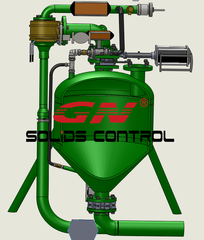
Working Principle
- Material Suction
High pressure and high speed air gets into thejet air tube assembly via inlet (high vacuum is produced by the air pocket in the jet air tube assembly) producing high vacuum in the tank for material suction.
Air enters into the distribution pocket via inlet, vacuum produced in the air distribution pocket.(when restricted flow passes the contractible cross section, flow speed will increase. Flow speed is inversely proportional to the cross section, the increasing of speed will go with reducing of fluid pressure. Low pressure will be produced near high speed fluids, then produce suction action)
When low pressure produced at the air pocket, the air in the tank flows towards the air pocket and gets out together with compressed air and then vacuum produced in the tank.
When pressure inner tank is lower than ambient pressure, material will gets into the tank under atmospheric pressure. (6-9 meters for water suction height delivery distance is different due to material density and viscosity)
- Material Discharge
- After suction process, compressed air flow direction changes and gets into the material storage tank.Pressure inside tank will be higher and higher finally the material is discharged out under high pressure and flows to distance with compressed air. (Max. Horizontal distance 500-1000 meters, delivery distance is different due to material density and viscosity)
When installing, need use different tube for feeding and discharge ,to make sure pump running well
Any problem about install and test running,please contact GN’s service and sales