The drilling operator might know that after several times reuse of the drilling mud, there will accumulate more and more ultra fine solids in the mud that cannot be separated out with physical method even by using high speed decanter centrifuge unit.
The accumulated solids will rise up the mud specific gravity that will greatly affect the mud performance. While, in order to keep the normal density of the mud, under this circumstance, the flocculation no doubt is the most popular method to be used.

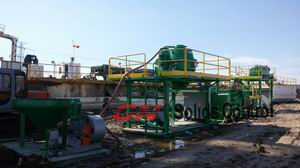
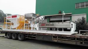
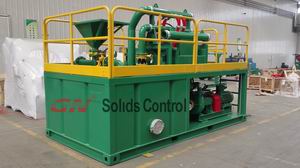
The flocculation process is produced in a type of machine called polymer mixing unit. This unit is used to mix the polymer that will be fed into the centrifuge to gather the fine solids in the mud. This polymer mixing unit is always connected with the centrifuge unit in the solids control system. After the separation by primary solids control equipment like shale shaker and cyclone unit, most of the solids larger than 5 microns could be removed out. The centrifuge unit plays an important role in this flocculation process. Sometimes, this centrifuge is called dewatering centrifuge.
GN’s polymer mixing unit is designed as 3 compartments mixing tank with automatic dosing conveyor and agitating device. Dry chemicals and water are fed into the first compartment for mixing, and then overflow into the second compartment for maturing process. The third compartment is used to store the solutions waiting for use.

The material of this machine body is PP. At each compartment, there is installed one automatic agitator with stainless steel made agitating shaft and impeller. The chemicals feed hopper is also made of SS304.
In order to realize the continuously mixing, the tank compartments are installed with liquid level control device. The mixing, maturing and storing process continuously transfer with low labor cost. The PLC design makes the operator adjust the solution concentration as per request, high automatic degree, and no need human watch over.
GN could provide the polymer mixing unit with dewatering centrifuge containerized for weather proof. For more information, welcome click to see GN Dewatering System.