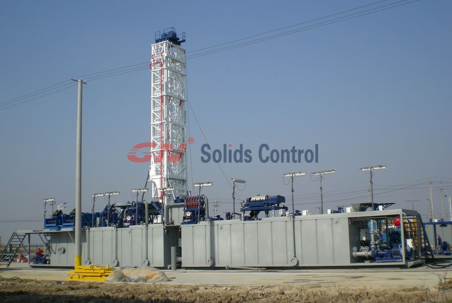
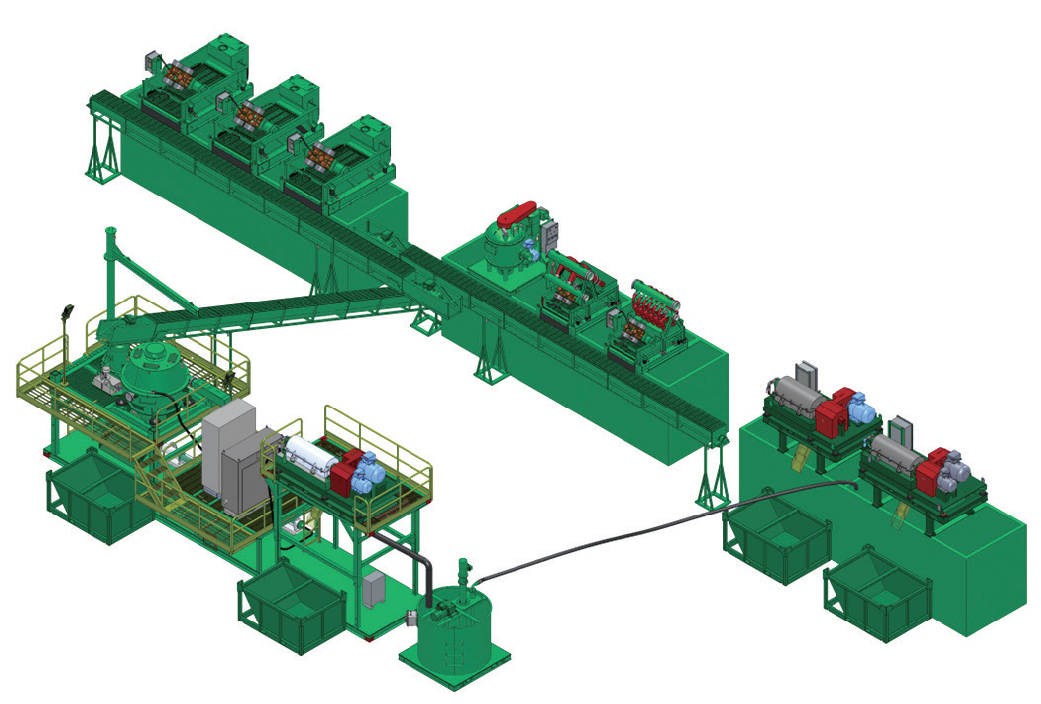
During the drilling process, a lot of hazardous waste will be generated, especially in the case of waste mud. This drilling waste will also be generated after the preliminary pretreatment of drilling equipment. The amount of suspended solids and fibers in the liquid is still relatively large. , Crown can use high-speed, ultra-high-speed centrifuges with filter equipment to separate harmful substances in the waste liquid, so as to achieve liquid recycling and pollution-free emission requirements.
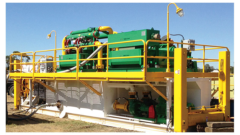
The quality of suspended particles in wastewater is different from that of wastewater, and the centrifugal forces encountered during high-speed rotation are also different. The centrifugal force of the large particle mass is large, and it is thrown to the outer circle of the centrifuge rotor of the drilling fluid and discharged downwards along the four walls of the centrifuge; while the small mass is left in the inner ring, it moves upward and the waste water and the suspended particles are separated. . The method is mainly used for removing the emulsified oil, fiber, and drilling fluid deposits in the waste liquid, and is mainly used for waste water pretreatment or intermediate treatment.
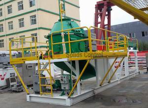
Centrifugal separation is a mechanical high-speed rotation separation method. Representatively it uses a drilling fluid centrifuge.

The GN solid control combined with the oil field unit did several experiments on the centrifugal separation treatment of the well team drilling waste liquid with different geological conditions without adding medicine. The experience is that the total rejection rate of the particles in the waste liquid from the liquid depends on such factors as the gradation of the particle size, the influent flow rate, the radial depth of water that the particles move in the equipment, and the residence time of the liquid in the equipment. Without additives and undiluted, 50 sets of tests with different rotation speeds and different residence times have shown significant effects in removing color and solid items. Under the condition of certain residence time, the rotation speed is best at 2500~3200r/min, and the change of water quality is not obvious when it is increased. However, when the rotation speed drops, the effect is reduced to a geometric multiple.
The results show that the treatment effect of drilling wastewater treatment using high-speed centrifuge separation is quite satisfactory.
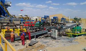
More detail,welcome to visit GN Solids Control


