First, the process
1, water-based drilling mud
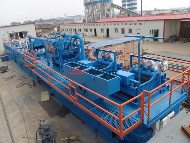
1 In the case of normal production of the well team solid control equipment, the cuttings discharged from the well team drilling fluid vibrating screen are sent to the drill cutting dryer for drying, and the solid granular mud generated by the well team shaker is processed. Cuttings are dried.
2Drill cuttings produced by the well team shaker are processed by the dryer drying unit. If they reach the standard, they can be discharged directly. If they are not up to the standard, they can be delivered to the first crucible (primary separation crucible) of the mud processing equipment. Dry the vibrating screen (with drill cuttings automatic curing system) for secondary drying. Cured and dried sludge can be directly discharged if it reaches the standard.
(3) The liquid phase discharged from the dryer and the mixed phase discharged from other solids and control equipment such as the de-sanding device, drilling fluid desilter, and drilling fluid centrifuge are uniformly transported to the second vessel (recovery and conditioning). Dosing modulation mixed stirring treatment.
4 The mud treated by the oil-recovering mash is transferred to the decanter centrifuge on the first rake for solid-liquid separation. The separated liquid phase is reused, and the solid phase enters the sludge conveyor and is sent to the automatic curing system. Drying treatment, treatment after the row.
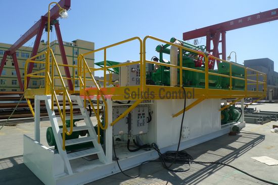
Automatic curing system
Spin-drying and solid-liquid separation systems
Social benefits and economic benefits of GN Solid Waste Management System:
Drilling waste mud or cuttings after processing by this device not only enables the drilling fluid taken away from the waste cuttings to be fully recycled, but also saves a large part of resources, and the treated solid objects reach the state’s regulations. The platoon standards, the indicators in the wastewater have reached the national levitation indicators.
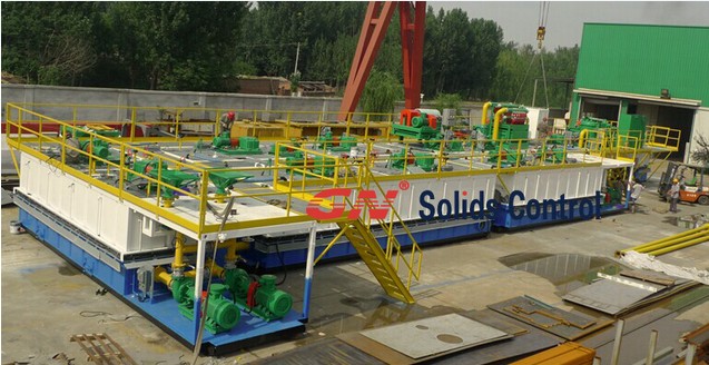
After several years of exploration and transformation, the skid-mounted drilling mud produced by our company is not a land-recycling treatment system, and it has been widely used in major domestic oil and gas fields.
At present, the skid-mounted drilling mud harmless treatment device produced by our company has been applied to more than one hundred wells, and it has finally passed the test. It has been unanimously recognized and praised by industry company leaders and experts. The company upholds the concept of integration and innovation, and continues to deepen the study of miniaturized skid-mounted harmless disposal equipment to create clean energy and build a harmonious society and natural environment for development goals. .
More question,welcome contact GN solids control